另一篇专利鱼骨垫文章于2014年12月在权威杂志Pumps & Systems发表,题为《一种能降低垫片压溃的革新设计》 副标题 -创新设计的"止压台阶"能有效增强垫片强度,减少泄漏!可索取“中文翻译版”。
Design Improvement Reduces Gasket Crush
A compressible design and stop-step enhances strength and reduces leakage.
By Justin Zhao Published in December 2014, Pumps & Systems, p78-81
Gaskets are crushed more frequently than many end users realize. Some maintenance professionals claim that is all they see when they separate a leaking flange. Many simply replace the gasket rather than investigating cause of the failure in depth.
Gasket crush is a significant threat to plant reliability. This problem causes leaks, which can lead to a dangerous plant situation, especially if a hazardous fluid is involved. This issue is unpredictable and introduces variability into plant operations.
All types of gaskets—metal, nonmetal and composite—experience gasket crush. If a gasket design fails on the first installation, plant personnel can replace it with a new design during the next plant shutdown. However, if a gasket has worked nine times without a problem, then leaks on the tenth installation because of gasket crush, an unplanned maintenance response is required.
Users have two options for reducing gasket crush: better torqueing procedures, which can be difficult and better gasket design, which is easier to implement.
Torqueing Procedures
In a crushed gasket, different compression patterns are visible—sometimes on one side of the gasket, sometimes on opposite sides and sometimes all over the gasket. These patterns point toward over-compression. The most obvious conclusion is that something was wrong with the torque, even though sophisticated torque equipment, such as torque wrenches or bolt tensioners, is often used during installation.
Torque equipment tensioning accuracy, which is generally between 5 and 15 percent at best, is based on a few important assumptions, including:
· Bolts must be well-lubricated with a lubricant of known coefficient of friction, because unlubricated bolts can consume up to 50 percent of the torque load.
· Torque typically is calculated based on the bolt material, not the required load of the specific gasket material, which is usually too high for the gasket need.
· Personnel only have access to a recommended bolt load for the cool flange when the operation has not yet started. The crucial hot torque load value is rarely available.
Maintenance workers torque flanges before plant startup, but when operational, flanges will expand because of process heat. Personnel must also perform a hot torque to prevent leaks. Torqueing practice in the field is based on skills and judgment.
Maintenance team members sometimes hot-torque a flange without a proper torque value for that temperature, and leakage persists. In this situation, maintenance personnel often continue to tighten the bolts until the leak stops. The gaskets are usually crushed at this point.
Successful flange hot torqueing is a disappearing art because of fewer senior maintenance staff who have had many years of experience performing the task.
Gasket Design
Designing better gaskets is a much easier solution in practice than attempting to deal with torqueing procedures and the art of hot torqueing.
Spiral-wound and camprofile gaskets are the most commonly used metal gasket types. The compressibility and elasticity of spiral-wound gaskets are useful sealing characteristics. When paired with the strength that a camprofile gasket achieves through its unitary metallic structure, gaskets start to approach optimal design.
These gasket types also have negative features—such as sealing issues—that should be addressed to improve gasket design. Both types also provide variable performance. Spiral wound gaskets have a tendency to unwind, and camprofile gaskets do not recover well. An improved design would also eliminate the flange damaging characteristics of both types by removing any sharp edges or points. The optimal gasket would be a solid, unitary metallic structure to prevent crushing. It would incorporate a mechanism for both compressibility and elasticity for improved sealing (see Figure 1).

Figure 1. Round-edged beveled ribs compress under pressure (Graphics courtesy of AIGI Environmental Inc.)
To achieve a crush-proof gasket, a simple feature called a stop-step can prevent over-compression of the flexible rib elements and eliminate the possibility of destructive compression of the overlaid sealing element. These stop-steps can be located outside the sealing area but between the flexible ribs for additional support (see Figure 2). An internal rounded stop-step, which is integral to the design, provides a positive stop that prevents over-stressing of the ribs and the graphite-sealing element.

Figure 2. A stop-step feature prevents the flexible ribs from over-compressing.
The stop-step ensures that the ribs remain elastic and functioning in their self-energizing capacity because it prevents them from being stressed beyond their elastic limit. The same is true for the graphite-sealing element. The ribs stop-step and graphite-sealing element perform as an integrated system to ensure maximum sealing performance under bolt load.
A gasket with this design is more difficult to make than constructing the concept. Designers cannot assume that any design element on its own will work. They must find a balance between the step height, the rib angle or curvature, and thickness to achieve optimal sealing while eliminating gasket crushing and sealing element over-compression.
The gasket prototype designs shown in Figures 1 and 2 were tested for crush resistance and sealing. The results confirm the effectiveness of the overall design and the specific utility of the stop-step (see Table 1 and Table 2).
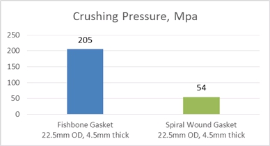
Table 1. Crush resistance test results, with a pressure of 205 MPa (29,732 psi)
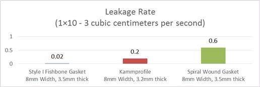
Table 2. A leakage Test compared the three gasket types. The gasket stress was 30 MPa (4,351 psi), and the nitrogen pressure was 4 MPa (560 psi)
The stop-step, which prevents gasket over-compression, can be applied to other types of gaskets. Both spiral-wound and camprofile gaskets can incorporate this design feature (see Figures 3 and 4).

Figure 3. Spiral-wound gaskets have a tendency to unwind.

Figure 4. Sharp edges in a camprofile gasket can lead to damage.
Gasket innovation is often a difficult and slow process because of the limited number of gasket features that can economically be incorporated in a design that must fit the space constraints between two flanges. These improvements are important as gaskets move toward the ultimate sealing reliability.
The stop-step design is one small step on the path to a new standard for metal gasket reliability.